How and why to add pull-up and pull-down resistors to Microcontroller I/O pins
Resistor "Pull-ups" and "Pull-downs" serve many purposes in electronics. A pull-up is a resistor with one end wired to a positive power rail. A pull-down has one end wired to ground or a negative rail. Here is a basic introduction with schematics. A wikipedia entry covers this but is full of arcana like ttl logic gates.
For Analog to Digital Convertor inputs they are often used to establish a controlled current flow into a resistive sensor such as a fabric pressure sensor, FSR (force (sic) sensing resistor) or LDR (light dependent resistor). A controlled current flow is required in these sensors because ADC's measure voltages so the Very Important Result (V=I.R) can be used to infer resistance from resistance changes. However the result is not a linear relationship between measured voltage and sensor resistance (the non-inverting op-amp is needed for that) but the low cost of resistors makes this a popular choice.
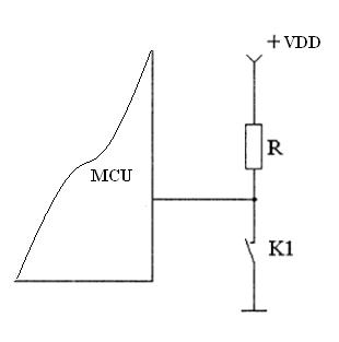
For switch inputs a pull-up can be used to establish a high or "1" value that the switch shorts to ground to establish the low or "0" value.
Pull-downs are often used on outputs to establish a known output impedance.
For digital I/O using the i2c protocol a pull up is used so that a single pin can serve as input or output.