CNMAT StompBox -- lots of pedals to Max
CNMAT StompBox -- a breakout box for Teensy & Max
Introduction
Early in the Fall semester 2017, CNMAT director Edmund Campion came to me with a request to build a system that would allow for multiple foot-pedal controllers to be connected to Max. The design criteria required that the system should:
- be lightweight
- be robust & durable
- allow for cable runs of 50’
- allow connection of a large number (10 or more) pedals of both the momentary (e.g. piano sustain) and continuous (e.g. expression/volume pedals) variety
- identify values with a unique OSC address inside of Max.
- simple to build with a minimum number of parts.
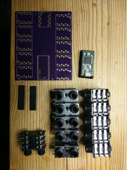
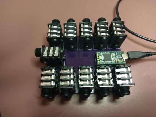
The solution I came up with is a simple breakout box, based on a Teensy 3.2 development board that allows for the simultaneous connection of up to 22 pedals (12 momentary and 10 continuous) using standard TS and TRS connectors in a small footprint. The Teensy is capable of powering long cable runs so all that is really needed is a breakout board for providing robust, professional terminations for the Teensy's pins. The resulting “CNMAT.o.stompbox” is a project designed to be simple to build, compatible with existing OSC-Arduino schemes (Oscuino, et al) while presenting minimal computational overhead to the Max environment. The breakout box can be used to provide a robust interface for any type of momentary switch or continuous controller that that can be wired into a TS or TRS connector and, as such, should find utility in a large number of performance and installation contexts.
Development of Breakout Board + Arduino Code
The design of CNMAT.o.stompbox began with breadboarding the Teensy in combination with various pedals in the CNMAT inventory patched through long cables. The pedals were connected to the various pins on the Teensy board and the Arduino software was written in such a way as to allow maximal flexibility and simplicity in breakout board design. Since the purpose of this box is to serve ridgidly as an input device, the Arduino code is as simple as it gets. The sketch simply sets all of the pins as INPUT_PULLUP, reads them in a constant loop, then formats and outputs these values over the serial port to Max. The INPUT_PULLUP mode was chosen for convenience and simplicity. Most pedals are of the “Normally Open” (+ polarity) and since the point of this project is to enable individual input from a large number of pedals, it was assumed that under normal conditions all of the pedals wouldn’t be depressed all at once (although they can be). INPUT_PULLUP mode uses the Teensy’s internal pull-up resistors to set each of its digital pins HIGH, so each input pin is normally sitting at +3.3 Volts relative to ground. Once an electrical connection is made from a given pin to ground, current flows and the state of that pin is reported as zero to the serial port. This results in inverted polarity, but simplifies the breakout board wiring since each digital jack only needs one board trace and one connection to the ground plane. The resulting inverted polarity is dealt with inside the CNMAT.o.stompbox abstraction.
The analog pins required a little more thought. Arduino devices, Teensy included, are designed to measure voltage varying between some reference and ground. Expression pedals are usually nothing more than a mechanism for controlling the bias of a potentiometer (voltage divider). As such, the Teensy analog inputs should be connected to the ‘wiper’ of the potentiometer biased between supply voltage and ground. This requires three electrical connections for supply (V+), ground (GND) and signal (Vs) to be carried over a standard Tip-Ring-Sleeve cable connector. Per standard convention, most pedals use 'sleeve' as ground. However, there is no standardization for the remaining two connections. Some pedals use the tip of the phone jack for supply voltage while others use the ring, so in designing the breakout board a choice had to be made. I ultimately chose to put supply voltage on the Tip connection and here is why: since this breakout box uses both TS and TRS connections, it is likely that at some point a TS cable will accidentally get connected to one of the analog TRS jacks. In this case, if the supply voltage were wired to the ‘ring’ connector, the insertion of a TS plug into a TRS jack would create a short circuit from supply to ground, thereby triggering the Teensy’s protection circuitry or, worst case, potentially causing damage to the board. By placing the supply voltage on the tip of the connector, we ensure that the device isn’t powered until the connector is fully inserted and a short circuit condition is avoided in the case of erroneous connection of a TS cable. However, this configuration does require that we choose the appropriate polarity of expression pedal for proper function. The pedal’s tip and sleeve connections should be connected to supply and ground and the ring should carry the variable voltage. The Yamaha FC-7 pedal is wired correctly for this configuration while the Roland EV-5 expression pedal will not work. Moog’s EP-3 has a polarity switch, so it can be configured for use with this setup.
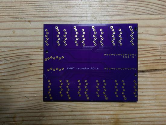
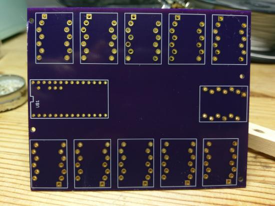
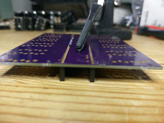
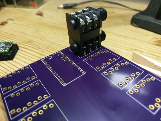
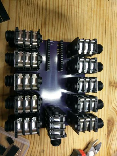
The breakout board was designed for use with Neutrik NSJ12HF-1 TRS Stacking Jacks which feature two switched jacks per footprint that accept threaded retaining nuts for panel mounting. In order to protect the Teensy board from excessive heat of soldering it is mounted on headers. There are no other components. Layout for the breakout board was designed in the free version of EAGLE using existing layouts from Teensy and Neutrik’s specifications for the NSJ12HF. For the prototype run, I opted for a single-sided board with ample spacing between components. PCB was sent for fabrication by OSH Park, which produces very pretty purple boards. The Eagle board files are provided below as part of the .zip download. Assembly is straightforward. Simply snap the components in place, solder and test. Once the other components are placed, holding the headers square and properly in place can be tricky, so I recommend soldering them first.
Max Abstraction
The CNMAT.o.stompbox Max abstraction is designed to simplify and automate the connection to the Teensy 3.2. It provides a means of calibrating the incoming signals from the various inputs in order to correct for differences in polarity and sensitivity and it formats the state of each input as an OSC address. This abstraction works in conjunction with the Arduino code running on the Teensy to efficiently transfer the state of each pedal input 100 times per second (it could be made even faster, if needed). Inputting the message "getports" to the CNMAT.o.stompbox object will automatically set the appropriate incoming port, finding the Teensy among the computer's various inputs. Once all pedals are connected the 'calDigital' message will set the base state of all connected momentary pedals. The 'calAnalog' message polls all of the analog inputs for a period of 10 seconds, during which time the pedal can be put through its entire range of motion. Thereafter, the value of the controller will be mapped as a float between zero and one corresponding to the controller's minimal and maximal value. The 'calAnalogTarget' message allows for the calibration of a continuous controller at a specific address. Once the CNMAT.o.stompbox has found the appropriate Teensy port, it will immediately begin reporting the states of the Teensy's pins by address. The digital pins appear on addresses /d0 through /d11 and the analog pins appear as /a0 through /a9.
Room for Improvement
This is just a simple prototype meant to solve a simple problem. However, in the design and building of this project I did identify several areas for improvement in future versions. First, having polarity switches or jumpers for the analog inputs would allow use with any expression pedal on the market. Second, in order to fit all of the components on the board area allowable in the free version of Eagle I had to put inputs on all 4 edges. This has made building an enclosure trickier than it should be. Future versions should have a different form factor to allow for a simpler housing design.