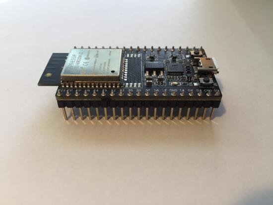
Stompbox 2.0 (2019)
The CNMAT StompBox 2.0 is being designed, programmed and assembled by Music and Computer Science major Luke Dzwonczyk with support from CNMAT's Jeremy Wagner and Professor Edmund Campion. Luke completed Music 158A and Music 158B which qualified him to participate in the Music and Technology "Discovery Experience", a CNMAT and Department of Music initiative to increase Undergraduate Research and Capstone projects involving music and technology at CNMAT.
Note: This project is currently in progress - this page will be continuously updated to reflect the latest stage of the project.
Summary
The CNMAT Stompbox, created by Jeremy Wagner in 2017, is a fully built and functional system for getting lots of switches into Max via USB serial connection. Initially conceived for foot pedal controllers, the CNMAT Stompbox provides robust TS & TRS connections for up to 12 momentary switches (such as sustain pedals) and 10 continuous controllers (such as expression pedals). A description of the Stompbox 1.0 and the process of creating it can be found at https://cnmat.berkeley.edu/projects/cnmat-stompbox-lots-pedals-max
The upgrade to Stompbox 2.0 includes the following major design changes:
- replacing the USB serial connection with a networked connection, freeing the stompbox from being physically tethered to a computer
- handling the reading of pedal inputs and calibration logic with Arduino code instead of a Max patch
These changes involved replacing the Teensy board with an Espressif ESP32 wifi-enabled microcontroller, and using the builtin UDP and CNMAT created OSC libraries for Arduino.
Introduction
The problem that the second iteration of the stompbox attempts to solve is to reduce long cable runs. The Stompbox 1.0 connects to a computer via a USB cable. However, USB cables has a maximum distance of 15 feet. This presents a problem: if the computer is more than 15 feet from the pedals, then the stompbox cannot be located next to the pedals but must instead be near the computer. This forces the user to run all the pedal cables (which could be up to 22 cables) from the pedals to all the way to the stompbox, which could be many feet away. By removing the USB cable entirely, the stompbox can be placed on stage with the pedals and the computer can be virtually anywhere. This is what the stompbox 2.0 achieves by using an ESP32 micro-controller that has WiFi capabilities. Through the use of the OSC and UDP Arduino libraries, and Max's built in udpsend and udpreceive objects, OSC packets can be easily sent over the network from the stompbox to a computer.
The two major changes that were implemented were using WiFi instead of a USB cable to output data from the Stompbox, and replacing the logic done by a Max patch with Arduino code. The CNMAT.o.stompbox Max patch read the analog pins on the Teensy board and packed them into odot bundles that were the output of the patch. It also dealt with the calibration of the pedals. Now, the reading of the pins and the calibration logic is done in Arduino. The pins are read using the built-in function analogRead() and calibration is started when the ESP32 receives an OSC message from Max with the /calibrate address set to 1.
The OSC Library
A major part of this project is sending OSC messages between the ESP32 and Max. This was all done using the Arduino OSC library written by Adrian Freed. The implementation is quite simple. First, an OSCBundle object is created.
OSCBundle bndl_out;
Then, when a value is read off the ESP32, an OSCMessage object is created and added to the bundle using the OSCBundle.add() function.
bndl_out.add("/digital/0").add(1);
Once all the OSC messages, one for each input, are added to the bundle, it is sent out using the OSCBundle.send(WiFiUDP) method.
bndl_out.send(Udp);
Calibration
Both digital and analog pins need to be calibrated. Calibration is necessary because the stompbox works with a variety of different brands and types of pedals, and we cannot assume that each pedal interacts with the ESP32 in the same way. Calibration begins when the ESP32 receives an OSC message with the /calibrate address set to 1. At that point, a calibration period of 10 seconds begins.
In the loop() function, UDP waits to receive and parse a packet from Max. When it does, it reads in the UDP packet as an OSCBundle, then calls dispatch() to call the method calibrate.
OSCBundle bndl_in;

int bndl_in_size;

// If a UDP packet has been received, parse it

if ((bndl_in_size = Udp.parsePacket()) > 0) {

    // read in the UDP packet as an OSCBundle

    while (bndl_in_size--) {

        bndl_in.fill(Udp.read());

    }

    // Call the calibrate() method with an OSCMessage with address /calibrate

    bndl_in.dispatch("/calibrate", calibrate);

}
The calibrate method takes in an OSCMessage, which is passed as a parameter by the dispatch method. If the OSC message has /calibrate set to 1, it begins calibration by setting the time that calibration will end, then calibrating each digital pin (momentary pedal).
void calibrate(OSCMessage &msg) {

  calibration = msg.getInt(0);

  // Calibrate all digital pins

  if (calibration) {

    calibration_end_time = millis() + CALIBRATION_TIME;

    for (int i = 0; i < NUM_DIGITAL_PINS; i++) {

      digital_initial_state[i] = digitalRead(i);

    }

  }

}
For momentary (on/off) pedals, not all types will output a 0 when in the off state and a 1 when on, some do the opposite. When calibration begins, the value of each digital pin (which is either 0 or 1) is saved in the digital_initial_state array. Then, when that pin value is read, it is XOR'd with its calibration value in digital_initial_state. For example, consider a pedal whose off value is 1 and on value is 0. Without calibration, this pedal would report 0 when pressed, which is the opposite of what a user would expect. Therefore, by XORing this pedals value with its calibrated value of 1, we will get a correct output of 0 when the pedal is not in use and a value of 1 when it is pressed.
For continuous (expression) pedals, a range of values can be represented by the pedal. On the ESP32 a voltage between 0v and 3.3v will be read from the pin and reported as an integer from 0 to 4096. However, different types of pedals may not use this full voltage range. If a pedals full range was only represented from 0 to 2048 for example, then you wouldn't get the expected behavior when the pedal was at its highest level level since it would only report 2048, half of the maximum. Therefore, in the calibration phase the continuous pedals need to be put through their full range of motion. During this time the min and max output from each pedal is stored in the int arrays analog_min and analog_max. Then when the pedal's value is read, it is mapped from its actual range (that was calculated during calibration) to the expected range of 0 to 4096.
When we are in calibration mode, we update the min/max values for each analog pin (continuous pedal):
/* Calibrating analog pins */

for (int i = 0; i < NUM_ANALOG_PINS; i++) {

    int val = analogRead(i);

    analog_min[i] = min(val, analog_min[i]);

    analog_max[i] = max(val, analog_max[i]);

}
Then, when we are later reading the value of an analog pin, we need to map the actual reading from analogRead() in relation to our calibrated range:
/* Reading in analog pin values and adjusting based on calibration */

for (int i = 0; i < NUM_ANALOG_PINS; i++) {

    sprintf(addr, "/analog/%d", i);

    val = analogRead(i);

    val = map(val, analog_min[i], analog_max[i], 0, PIN_MAX_VALUE); //Map the reading based on calibration

    bndl_out.add(addr).add(val);

}
Testing Process
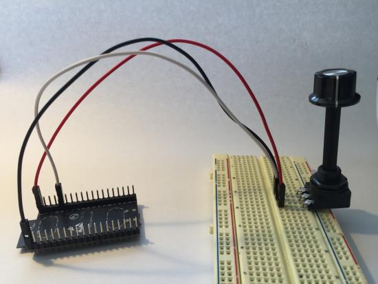
In order to mock a pedal for testing purposes, I used a breadboard to connect one of the pins of the ESP32 to a potentiometer. The dial on the potentiometer acts much like a continuous pedal, and the ESP32 will read this as a value from 0 to 4096. I created a simple Max patch that has a udpreceive object to receive OSC messages from the ESP32, then parses the addresses using the OSC-route object. This created a simple setup in which turning the potentiometer simulated a continuous pedal, and you would expect to see the values change in Max.
Next steps
The next steps on the software side are to allow multiple stompboxes to be used on the same network. This scenario presents a few problems. First, there is currently no way for Max to decipher which OSC messages are from which stompbox, since each one would be sending the same OSC addresses. Second, messages from Max to the stompbox are currently broadcasted on the network, meaning sending the calibration to one stompbox will send it to all stompboxes. This can be solved by specifying which stompbox you want to calibrate through its MAC address. With the MAC address, the IP of the stompbox can be retrieved, and the message can be sent to a specific stompbox.
The current CNMAT.o.stompbox Max object will need to be replaced with a much simpler object. It will receive the UDP packet and route the values. Once the logic for having multiple stompboxes is figured out, this object will have to deal with taking in the IP of the stompbox you want to send to/receive from and correctly output values
The stompbox 2.0 also needs to be fabricated. This involves creating a PCB with the correct dimensions to use the new ESP32, since it is a different size than the Teensy board used in version 1.0. Other additions in the future could include adding a small display to the stompbox. This could help the user identify the IP address of the stompbox, which would get rid of the need to identify stompboxes by their MAC address. The display could also tell the user when it is in calibration mode and help debug any problems that arise during its use.


